Barry Milder, MD
Introduction
Accuracy in objective refraction (retinoscopy) relies on the retinoscopist's abilities or the autorefractor's software. However, subjective refraction involves complex interaction between a refractionist and a patient that achieves its endpoint from the patient's responses to the refractionist's questions. Subjective refraction should be a sequence of steps that, when properly performed with a cooperative patient, elicits the most accurate report of the lenses that provide the best visual acuity for the patient. While most of refractionists' time is spent refracting for distant targets, the same techniques may be applied to determine corrective lenses for near vision. Occasionally, a significant difference in the distance and near corrections causes visual symptoms.
In its most reduced form, subjective refraction comprises determination of an initial estimate of refractive error, refinement of corrective lenses, and checking the accuracy of that refinement.
The initial estimate of refractive error is most often obtained from retinoscopy or measurement of the patient's spectacle lens powers on a lensometer. Less often, the astigmatic dial may be chosen. Allowing the patient to spin the phoropter sphere and cylinder dials searching for lenses that improve vision is least beneficial and fraught with the greatest risk of error. The latter approach will often result in more time required refining the starting estimate than any of the other methods mentioned. (Retinoscopy and optics of the lensometer are reviewed in other Tutorials.)
Astigmatic Dial
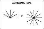
The astigmatic dial found on most projectors is either a full or upper-half clock face with lines radiating from the center at each hour (Slide 1). The dial is useful for determining refractive error, including the presence of astigmatic refractive error and its approximate axis and power. An eye with astigmatism focuses targets better if they are parallel to the focal line of the conoid of Sturm which is closer to the retina. Such eyes will have more difficulty seeing targets that are perpendicular to the focal line closer to the retina. Use of the astigmatic dial is based on this knowledge.
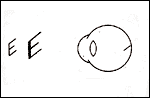
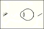
Consider the retina as a screen on which lines in the environment are being projected. The image of the lines will be determined by the position of the conoid of Sturm. If the retina is closer to the anterior focal line of the conoid of Sturm (Slide 2), then all points on all lines (or any target) in its view will be imaged as ovals with the long axes parallel to the anterior focal line.
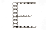
Slide 3 demonstrates the following discussion. If the anterior focal line is horizontal, the oval image of each point on the horizontal arms of the E will have its long axis parallel to the horizontal arm, and the arm will be blurred by the short axis width. The vertical arm of the E will also have every point imaged as a horizontal oval, but those ovals are stacked one atop the other, causing the vertical arm to be blurred by the long axis of the oval. Therefore, the vertical arm is seen with a much greater degree of distortion than the horizontal arms.
The astigmatic dial presents a patient with lines at the clock hours (every 30°); the lines that align closest to the axis of the patient's astigmatic error will be the clearest (Slide 4). When a patient indicates the clearest line, the refractionist does not know if that line is the anterior or posterior focal line of the conoid of Sturm.
Therefore, the eye is overplussed, called "fogging," to produce a condition in which the posterior focal line is the line closer to the retina. Generally, the refractionist adds plus
lens power before the patient's eye until vision is blurred to 20/50 to 20/100. If the patient is myopic, the eye is already fogged and minus lenses may be required to improve vision
to the 20/50 to 20/100 range. Myopia may be presumed when the patient's vision is blurred for distance vision, but clear for near vision.When the eye is fogged, the clearest line
on the dial is known to be parallel to the posterior focal line (Slide 5).
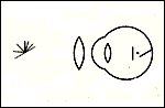
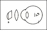
If a refractionist is working with plus cylinder correction, the cylinder lens is placed with its axis parallel to the clock hour that
the patient reports is clearest in the fogged state (Slide 6). As the plus cylinder power is increased, it will act on the focal line
parallel to its axis, the posterior line, and will not move the anterior line. This will progressively collapse the conoid of Sturm, reducing the uncorrected astigmatism,
but it will also progressively increase the fogging blur, as the circle of least confusion moves toward the anterior focal line by half the amount the posterior line moves.
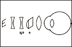
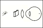
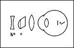
To allow the patient to identify changes in vision based only on changes in amount of astigmatism and not become confused by increasing fogging, the fogging sphere
is made more minus by half the amount of the plus cylinder added (Slide 7). When the patient reports that all the clock hours are equally blurred,
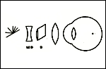
the astigmatic interval has been collapsed, and only a spherical error remains, the amount of fog (Slide 8). The sphere power is adjusted more minus
until the patient reports best visual acuity (Slide 9).
If a refractionist is working with minus cylinder, the corrective cylinder lens is placed with its axis perpendicular to the clock hour that the patient reported as clearest, that is, parallel to the anterior focal line. When the cylinder power is increased, it pushes the anterior line toward the posterior line (Slide 10). Because the fogging is not increasing as the cylinder is increased, no compensation in sphere power is necessary. When the patient reports that all clock hours are equally blurred, there is no residual astigmatic error, and the sphere can be made more minus until best visual acuity is achieved.
Refinement of Sphere
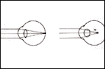
Once an estimate has been determined by any of the methods mentioned, the refractive correction should be adjusted to place any uncorrected astigmatic interval
with its circle of least confusion on the retina (spherical equivalent error of 0). Mistakes in this step are most often due to accommodation. Accommodation may be the most significant development in vision since color perception, but accommodation is the bane of refractionists. Inappropriate accommodation during refraction produces a pseudo myopic shift in focus (Slide 11). It is especially problematic in pre-presbyopic patients. To reduce the tendency to accommodate, the refractionist may fog the opposite eye, rather than occlude it. Most patients can tolerate 6 D to 10 D of overplussing of the opposite eye when the eye being refracted has good vision.
If the patient's acuity with the estimated correction is 20/20 before an adjustment of sphere component, the sphere should be adjusted plus until the acuity drops slightly. This minor fogging will ensure that the refinement process is not starting with the eye in an overminused state and with the patient already accommodating to compensate for the excess minus power in front of the eye. After the slight fogging, the new sphere power is adjusted by adding minus power, while asking the patient to report acuity at every step. The sphere change is ended when the patient stops identifying smaller letters, not when the patient reports that the letters are becoming more unclear. Adding minus beyond the first power that achieves best acuity is likely to be overminusing, inducing an accommodative response. When the patient accommodates while viewing a distant target (e.g., the Snellen chart), the target appears to slightly minify, darken, and become more highly contrasted. As the patient approaches best visual acuity, the refractionist should ask patients about such observations.
Cross Cylinders
As discussed in the section "Astigmatic Dial," any change in position of one focal line changes the position of the circle of least confusion by half the movement
of the focal line. The new spherical equivalent may be farther from the retina, and may blur a patient's vision, even if the astigmatism has been reduced.
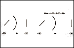
Slide 12 shows that effect, as the astigmatic interval of 4 D is reduced to 2 D by the addition of a simple cylinder lens of plano -2.00 x 180, but
the vision has been blurred by pushing the focus 1 D behind the retina. It would be difficult for the patient to tell the refractionist that the plano -2.00 x 180 lens is acceptable for
reducing the astigmatic error, although it is.
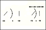
A cross cylinder is a lens that has sphere power one half of the cylinder power and of opposite sign, that is, -A + 2A x (any axis). The cross cylinder lens will change the amount of astigmatism by the cylinder power in the lens, but will keep the circle of least confusion unmoved because of the compensatory adjustment of the sphere power by half the cylinder power. In Slide 13, the +1.00 - 2.00 x 180 cross cylinder reduces the amount of astigmatism by 2 D, just as did the plano -2.00 x 180, but the +1.00 - 2.00 x 180 cross cylinder keeps the focus on the retina and the patient can report improved acuity. If the cross cylinder is flipped 90° (Slide 14) to become +1.00 - 2.00 x 90 (same as -1.00 + 2.00 x 180), then the amount of astigmatism is increased by 2 D without changing the spherical equivalent, and the patient reports decreased visual acuity.
Refining Cylinder
Once the spherical error has been refined, the axis and power of the corrective cylinder lens must be refined with the cross cylinder lens. The visual acuity after sphere refinement should be determined. The patient's attention should be directed to letters one or two lines larger on the Snellen chart, because even if the corrective cylinder lens is perfect, the introduction of the cross cylinder will blur the patient's vision somewhat.
Cylinder axis is usually refined before cylinder power, but power refinement is the basis for both.
Refining Cylinder Power
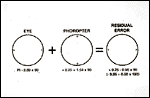
When the axes of two cylindric lenses are aligned, the resultant effect is additive. When the eye's cylindrical error and the corrective lens are properly aligned but not of the same power (Slide 15), the residual error is the sum of the two cylinder components.
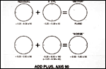
Any residual uncorrected cylindrical error may be identified and eliminated with the cross cylinder, using it with its axes aligned with the axis of the corrective lens in the phoropter (or trial frame). Flipping the cross cylinder will add or subtract its cylinder power over the phoropter's cylinder power over the eye's cylindrical error, without changing the spherical correction. If the patient's vision is improved with the cross cylinder's plus axis aligned with the corrective cylinder's axis (Slide 16), plus cylinder power is added to the phoropter's cylinder. If vision improves when the cross cylinder's minus axis is over the corrective lens' axis, minus cylinder power is added to the corrective cylinder (or decrease plus). The spherical equivalent (circle of least confusion) will change by half the change of cylinder power, so the corrective sphere power must be altered -0.25 D for every +0.50 D change of cylinder power, or +0.25 D for every -0.50 D cylinder change.
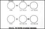
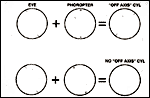
When the corrective cylinder's power matches the eye's cylinder error, there is no longer a residual cylinder error. Flipping the cross cylinder will present equal blur to the patient, who should indicate no difference between the two cross cylinder positions (Slide 17).
Refining Cylinder Axis
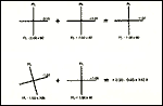
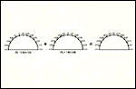
As long as two cylinders (e.g., the eye and the corrective cylinder lens) have aligned axes, the result is additive. However, when two cylindrical lenses have similar power but the axes are not aligned one atop the other (Slide 18), the additive result is not a simple cylinder, but it has a new sphere and cylinder, with axes 45° from the bisector of the two cylinders' axes. While the resultant powers are not intuitively obvious from the original cylinders, they are nonetheless obtained by addition of the two axes. This can be illustrated by adding to the diagram of the lenses the powers at multiple meridians on their surfaces (Slide 19). The resulting diagram shows that the maximum and minimum powers of the combination of the two cylinders are approximately 45° from the bisector of the original two axes. If the sphere component is separated from the resultant, the cylinder is left (Slide 20).
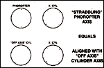
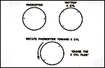
If a cross cylinder lens is placed with its axes 45° from the phoropter's corrective cylinder axis (straddling), the cross cylinder will almost align with the resultant error's axis (Slide 21). In essence, refining the corrective cylinder's axis is a power refinement of the resultant error. Flipping the cross cylinder will increase or decrease the resultant error's cylinder power (Slide 22). The phoropter's corrective cylinder axis is rotated in the direction of the cross cylinder's axis, when the cross cylinder is in the position that the patient reports as providing better acuity (Slide 23) (plus corrective cylinder follows cross cylinder plus axis, minus "chases" cross cylinder minus axis). When the corrective cylinder's axis matches the eye's cylinder axis, there is no longer a "new" cylinder induced by having misaligned axes, and flipping the cross cylinder will present the patient with equal blur (Slide 24).
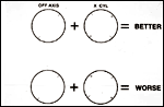
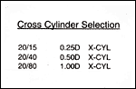
Whether refining the corrective cylinder axis or power, the power of the cross cylinder should vary with the patient's visual acuity. The two cross cylinder positions, aligning the plus or minus axes with the corrective cylinder axis or the "new" cylinder axis, only increase or decrease the patient's visual acuity by the amount of cylinder power in the cross cylinder. The change of 0.50 D cylinder in a 0.25 D cross cylinder will be readily apparent to most patients with 20/25 or 20/20 vision, but will not be resolvable by patients with poor acuity. Therefore, a stronger cross cylinder must be used when acuity is low (Slide 25). If the patient's acuity improves as the refraction proceeds, the refractionist should return to the weaker cross cylinder to obtain a more accurate end result.
Bibliography
The American Academy of Ophthalmology. The Revised 2000-2001 Basic and Clinical Science Course. Section 3: Optics, Refraction, and Contact Lenses. San Francisco, Calif: The Foundation of the American Academy of Ophthalmology.
Gettes B. Practical Refraction. New York, NY: Grune and Stratton; 1957.
Michaels D. Basic Refraction Techniques. New York, NY: Raven Press; 1998.
Milder B, Rubin M. The Fine Art of Prescribing Glasses Without Making a Spectacle of Yourself, 2nd ed. Gainesville, Fla: Triad Publishing; 1991.
Miller D. Textbook of Ophthalmology. Vol. 1. Optics and Refraction. New York, NY: Gower Medical Publishing; 1992.
Rubin M. Optics for Clinicians, 2nd ed. Gainesville, Fla: Triad Publishing; 1993.
Sloane A, Garcia G. Manual of Refraction, 3rd ed. Boston, Mass: Little Brown and Co; 1979.
Tasman W, Jaeger E, eds. Duane's Foundations of Clinical Ophthalmology. Vol 1: Refraction and Clinical Optics. Philadelphia, Pa: Lippincott-Raven Publishers; 2000.