Prisms
Light passing through a flat (planar) interface between media of different refractive indices is refracted without change of vergence. At a curved surface, vergence would be altered. If an optical medium is limited by two parallel flat surfaces (e.g., window glass), light is refracted when passing through the first surface (Slide 1). At the second surface, it is refracted in the opposite manner because the angle of incidence is the same as the angle of refraction at the first surface. Light exits the delimited medium traveling in the same direction as it was before entering and without change of vergence. If the two parallel surfaces are curved (Slide 2), the exiting light will have different vergence from that of the incident light, but the focal point still will be found along the ray of incident light that passes through the nodal point of the two surfaces. The direction of the focus will not have changed, but its distance from the position of the curved surfaces will have changed.
If the limiting surfaces are planar but not parallel (Slide 3), vergence will not be modified as light passes through, but direction will always change because the angle of incidence at the second surface will never equal the angle of refraction at the first. The two nonparallel surfaces create a prism. Where the two surfaces meet is the apex of the prism. The direction opposite the apex is the base. Light entering one side of the prism will be deflected from its original path toward the base.
The greater the angle between the two surfaces, the more the light will be deflected (i.e., the greater the prismatic power). A prism that changes the direction of the incident light by 1 cm at 1 m from the prism (Slide 4) is defined as having a power of 1 prism diopter, abbreviated Δ or PD to differentiate from the diopter of vergence power. The relationship of angle of deflection of light to prism power is not a constant. For low-power prisms that redirect incident light up to 15°, each degree corresponds to about 1.75 Δ. From 15° to 30°, the relationship is closer to 2.0 Δ per degree. At larger angles, the prism diopters per degree increase significantly. Most textbooks use the approximation of 2.0 Δ per degree.
If a target is viewed through a prism, the deflection of the light from the target will make it appear to be moved toward the apex of the prism, relative to its true position (Slide 5). The greater the prism power, the farther the image is from the object's actual position. The rules to remember are that light is deflected to the base and image is deflected to the apex.
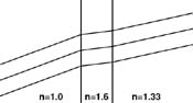
The previous paragraphs (and those that follow) have assumed that the same refractive index exists outside both limiting surfaces and that the refractive index between the two limiting surfaces is greater than the surrounding medium (i.e., the prism is denser than its surroundings). If these assumptions are not maintained, interesting things occur. For example, if the medium between two nonparallel surfaces has a lower refractive index than the surroundings (Slide 6), light would be deflected toward the apex and image toward the base, opposite the usual textbook dogma. Even parallel planar surfaces can produce a prismatic effect if the surrounding media are of different refractive indices (Slide 7). Incident light perpendicular to the surfaces would not be deviated, but as the angle of incidence is increased, the exit angle is increasingly different from the incident angle. However, it is best to ignore such oddities and concentrate on the typical prisms utilized in clinical practice.
Fresnel Prism
Prism power is the same at all points
on nonparallel surfaces, whether light is incident at 0.5 mm from the apex or
9/10ths of the way to the base. The apex even could be cut off, leaving a
trapezoid, with prism power unchanged. A Fresnel prism is a series of small
prisms of identical apical angle and, therefore, identical power, that are
adjacent to one another's apex to base on a carrier of zero refractive power
(Slide 8). Because the small prisms cover the entire
surface of the carrier, all incident light will be deflected identically as
though a single prism as large as the carrier was present. However, a single
prism of that size would be much thicker and heavier than the Fresnel prism.
Fresnel prisms made of flexible plastic are available in powers up to 30 Δ. They may be cut with scissors or a sharp blade, and will adhere well to either the concave or convex side of spectacles, although they most often are applied to the former. By cutting the appliqué appropriately, prism may be added to any spectacle at any orientation, and often at lower cost than prism ground into the spectacle lens. However, Fresnel prisms are prone to peeling off glasses and air bubbles may develop between the two materials. Even without such problems, Fresnel prisms always reduce visual acuity due to diffraction from the prism angles and to imperfections in the soft plastic.
Induced Prism
Lenses with refractive power also
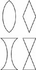
have prismatic effects. If the cross section of a simple plus lens (Slide 9,
top) is examined, the outer rim resembles two prisms placed base to base,
although the sides are curved, not flat. Minus lenses are similar to prisms
placed apex to apex (Slide 9, bottom). A segment of
the lens near its optical center is similar to a trapezoidal piece of a prism
(Slide 10). The tangents to the curved sides of the
lens at any point would most closely approximate the sides of a prism similar
to that part of the lens. The angle between the tangents is zero at the optical
center of the lens and increases as one views closer to the edge of the lens.
Thus, the prismatic effect is greater, or farther, from the optical center.
This relationship is described by Prentice's Rule:
Δ = h times
D
The prism diopters induced by viewing through a lens equals the product of the distance from the optical center of the lens (h) in centimeters times the dioptric power of the lens (D). Viewing 10 mm (1 cm) from the center of a +10.00 D lens would result in a 10-Δ displacement of the image, whereas viewing 25 mm off-center would cause 25 Δ image displacement (Slide 11).
Induced prism may be a significant problem if glasses are fitted poorly and is often a challenge in the management of patients with anisometropia (see Anisometropia Tutorial ). However, it may be used in a positive way to reduce some strabismic symptoms. An exophoric hyperope could be offered spectacles with optical centers closer than the interpupillary distance, inducing base-in prism for distance vision. A myope's optical centers would exceed the interpupillary distance to achieve similar base-in prism. In either myopes or hyperopes, decentration of bifocal segments closer than normal would induce base-in prism for reading without prism for distance vision.
Prisms in Practice
Although a prism is usually
thought of as having a fixed power, in reality, two planes of stable apical
angle will deflect light a different amount varying with the angle of incidence
of the incoming light. The minimum angle of deviation occurs when equal bending
(i.e., refraction) takes place at each prism surface (Slide 12, center). Any other angle of incidence results
in greater deviation, such as the Prentice position (Slide 12, left), which is when light is perpendicular to
one of the prism surfaces. Most ophthalmic prisms, as well as glass orthoptic
prisms, are calibrated for use in Prentice position (i.e., with the back
surface perpendicular to the visual axis). Plastic prisms are calibrated to be
used at the minimum angle, best approximated by holding the back surface
parallel to the facial plane.
The presence of prism in spectacles may be suspected by the observation of a marked asymmetry in the thickness of the nasal edge of the lens versus its temporal edge, or superior versus inferior. In addition, if lensometry finds that the optical center of the spectacle lens lies significantly away from its physical center, prism is probably present. Either ground-in or induced prism may be measured by marking the visual axis on the spectacles with a grease pen or felt tip pen and then viewing that spot at the lensometer.
Image Displacement and Image Jump
Image
displacement occurs when induced prism causes a target to appear in a different
position from where it actually exists. Patients who wear spectacles experience
image displacement in all positions of gaze, except when an eye is looking
through the optical center of the lens before it. Although most textbooks
concentrate on image displacement when reading, identical displacement occurs
in upgaze and lateral gaze. If a patient with -5.00 D OU looks 10 mm above the
optical centers of his or her spectacles (Slide 13),
each of the patient's eyes is looking through 1.0 cm x 5 D = 5.0 Δ
induced prism, base-up. If the object of regard is 1 m away, the patient would
need to aim his or her eyes at a spot 1 m x 5 Δ = 5 cm below the object's
true position to see it. If the target is 50 m away, its image would be 2.5 m
displaced. If a patient with -5.00 D OU looks 10 mm down through +2.00 D
bifocals, overall image displacement would be governed by the total power at
that position, or -3.00 D x 1.0 cm = 3 Δ. If there is no anisometropia,
image displacement may produce some difficulty when the patient reaches for
objects, but little other nuisance. However, with anisometropia, the asymmetric
image displacement, known as anisophoria, may cause bothersome symptoms (see
Anisometropia Tutorial
).
When the -5.00 D OU presbyopic myopic patient's eyes cross from the distance correction into the bifocal, they will instantaneously encounter prism induced by the bifocal's power because the line of sight is not passing through the bifocal's optical center. If the top edge of the bifocal is 7 mm below the optical center of the -5.00 D spectacles, immediately above the bifocal the patient has 3.5 Δ base-down image displacement. If the bifocal is a 22-mm round seg, its optical center is 11 mm below its upper edge, and it induces 1.1 cm x 2.0 D = 2.2 Δ base-down at its edge. As the eyes move into the bifocal, the targets they are viewing appear to abruptly shift upward from the 2.2 Δ induced (Slide 14, left), and this is image jump.
Image jump is maximal with round segs, less with flat top segs (Slide 14, right), and nonexistent with executive segs because the optical centers are at the edge of the bifocal. However, for a myope, image jump is in the same direction as image displacement and magnifies the difficulties knowing where the target is positioned. For a hyperope, image jump reduces the overall displacement of the target. Patients with myopia may do best with flat top or executive bifocals. The choice of bifocal for patients with hyperopia is less certain. In practice, most patients choose what they prefer and adapt to the resultant prismatic effects.
Ring Scotoma
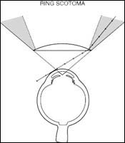
An exaggerated example of image
displacement is the ring scotoma encountered by wearers of high plus spectacles
(Slide 15). The considerable prism induced in the
lens periphery results in a zone of the visual field prismatically shifted
outside the entry pupil of the eye and therefore not seen. Objects within this
zone are invisible in this ring scotoma that shifts position as the line of
sight moves behind the glasses. While the ring scotoma is usually discussed in
association with aphakic spectacles, it is a phenomenon with any plus lenses of
significant power.
Mirrors
A mirror is a reflective surface that folds image space back onto object space. Therefore, the optical properties of mirrors are identical to those of lenses. The vergence of light striking a mirrored surface plus the effect ("power") of the surface will produce the vergence of the reflected light. Flat planar mirrors will add no vergence to incident light. Curved mirrors, like curved lens surfaces, will alter the vergence of light striking the mirror. However, rather than Snell's law, which applies to interfaces through which light is refracted, the constant feature of all mirrors is that the angle of incidence equals the angle of reflection, the two angles being measured relative to the perpendicular surface of the mirror at the point of reflection.
Plane Mirrors
As mentioned above, a flat plane
mirror does not change the vergence of light striking its surface (i.e., it has
no power). The vergence formula

is still applicable. U is object vergence, D is power and V is image vergence, but D is zero. Because image vergence V equals object vergence U, the image distance (1/V) will equal the object distance (1/U). The plane mirror will create an upright, virtual image that will appear to be as far behind the mirror as the object is in front of the mirror. Image location may be found by following any reflected ray back into the virtual space behind the mirror to the point where it intersects the ray from the object perpendicular to the mirror (Slide 16).
Curved Mirrors
Like curved refractive surfaces,
curved mirrors alter the vergence of light that strikes them. The degree to
which vergence is changed (i.e., the power of the reflecting surface) depends
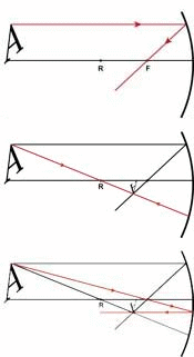
on the curvature of that surface. As with lenses, primary focal point (F) is
defined as the point at which light would originate, such that it has zero
vergence in image space (Slide 17, bottom ray), and
has secondary focal point (F') at which incident light from infinity (zero
vergence) would be focused by the mirror (Slide 17,
top ray), but F and F' will always be in the same place due to the reflection
of image space onto object space.
The distance of F/F' from the mirror is the focal length (f) and the power of the mirror is 1/f, like refractive surfaces. But f will always be one-half the radius of curvature of the mirror surface, as demonstrated in Slide 18. Observe that any ray parallel to radius RA will be reflected (for example at point S) back through the focal point F, which is also the position of F' (Slide 18, left). The angle of incidence, <OSR, at point S will equal the angle of reflection, <FSR, but also will equal angle <FRS because alternate angles of line RS intersecting two parallel lines OS and RA are by definition equal. Because angle <OSR = <FRS = <FSR, then triangle FSR is an isosceles triangle with legs RF and FS of equal length. As point S is brought closer to point A (Slide 18, right), RF plus FS approximates a radius. When S superimposes A, the length FS is seen to be one-half of the radius of the mirror's curvature, RA. Therefore, the mirror's power D equals -1/f = 1/(1/2 radius) = -2/r.
The basic vergence formula U + D = V also applies to curved mirrors as to plane, and D = -2/r. It must be remembered that r is minus for concave mirror surfaces (like concave refractive surfaces) and plus for convex mirror surfaces. This allows one to utilize the same U + D = V formula for lenses and mirrors. Because D = -2/r, concave mirrors, which have negative r, add plus vergence to incident light and magnify, whereas convex mirrors minify by adding minus vergence.
Image location with curved mirrors, as with lenses that refract, is determined by vergence in image space. If an object is 20 cm from a convex mirror of 10 cm radius (Slide 19), U + D = V gives -5 + (-2/0.1) = -25 D. The virtual image will be 1/25 m, or 4 cm, behind the mirror. Because image size is related to object size as image distance is related to object distance, the image will be 4/20, or 1/5 the size of the object. Image position and size also could be determined diagrammatically. Any ray from the peak of the object A parallel to the horizontal will be reflected through focal point F/F' (Slide 20). The central ray of any mirror passes from the object point A through the center of curvature of the mirror and, therefore, is along a radius. It will be perpendicular to the mirror where it strikes and will be reflected back along the same path. Where these two rays meet is the image point corresponding to the apex of the object A. Incidentally, the ray passing from point A through the focal point F/F' will be reflected parallel to the horizontal and also back through the corresponding image point.
Summary
Prisms:
- Light is deflected to the base. Image is deflected to the apex.
- 1 cm deflection at 1 m is 1 prism diopter (Δ). 1° equals approximately 2 Δ.
- Prentice's rule (h x D = Δ) defines induced prism.
- Use glass prisms with back surface perpendicular to visual axis. Use plastic prisms with back surface parallel to facial plane.
- Image displacement occurs with any lens of significant power when viewing outside of optical center.
- Image jump is of variable significance, greatest with round bifocals on myopic spectacles.
Mirrors:
- Plane mirrors have no power. Image is behind mirror as far as object is before mirror.
- Power of curved mirror is -2/r. Concave mirror r is minus. Convex mirror r is plus.
- Image location with curved mirror is 1/image vergence (in air).
- Image size with curved mirror is object size times (image distance/object distance).
Bibliography
American Academy of Ophthalmology. Basic and Clinical Science Course. Section 3: Optics, Refraction, and Contact Lenses; 2000-2001.
Tasman W, Jaeger E, eds. Duane's Foundations of Clinical Ophthalmology. Vol 1: Refraction and Clinical Optics. Philadelphia, Pa: Lippincott-Raven Publishers; 2000.
Miller D. Optics and Refraction: A User-Friendly Guide. New York: Gower Medical; 1992.
Rubin M. Optics for Clinicians, 2nd ed. Gainesville, Fla: Triad Publishing; 1993.